AI-Powered Flotation Optimization with a Polish Pilot at KGHM
The Mine.io project is focused on developing a new Holistic Digitized Ecosystem of the Mining Industry 4.0. Its aim is to propose a new organization of the extraction, processing and use of mineral resources.
This approach has been forced by the changes brought about by the Fourth Industrial Revolution (Industry 4. 0) and the introduction of Internet of Things (IoT), Artificial Intelligence (AI), Big Data, Machine-to-Machine communication (M2M) and cloud computing.
These technologies are forcing significant changes to the mining and mineral processing industries, as well as their significant digitalization to improve productivity, financial ratios and reduce the industry’s negative environmental impact.
The Polish part of the Mine.io project consortium (Team) consists of Łukasiewicz – ITR, KGHM, Łukasiewicz – EMAG and AGH. Our efforts are focused on the new approach to optimisation of the flotation technology. These activities are carried out as part of Task T4.3 within Work Package 4 of the Mine.io project. It is based on application of the Machine Learning (ML) and (AI) technologies for the assessment of a flotation froth image for the prediction of the froth content. Such approach will help us to understand the flotation process and to find the better way for this process optimisation.
Main efforts are focused on development of the Photonic – IT (PIT) System and its installation at KGHM. This System is destined for the froth image registration, image processing, calculation image descriptors and then to carry out the ML process that will create the relation between the froth image and the froth content. On this basis, the AI will construct algorithms for the froth content estimation and then for an AI-assisted Ore Flotation Process Optimization and control.
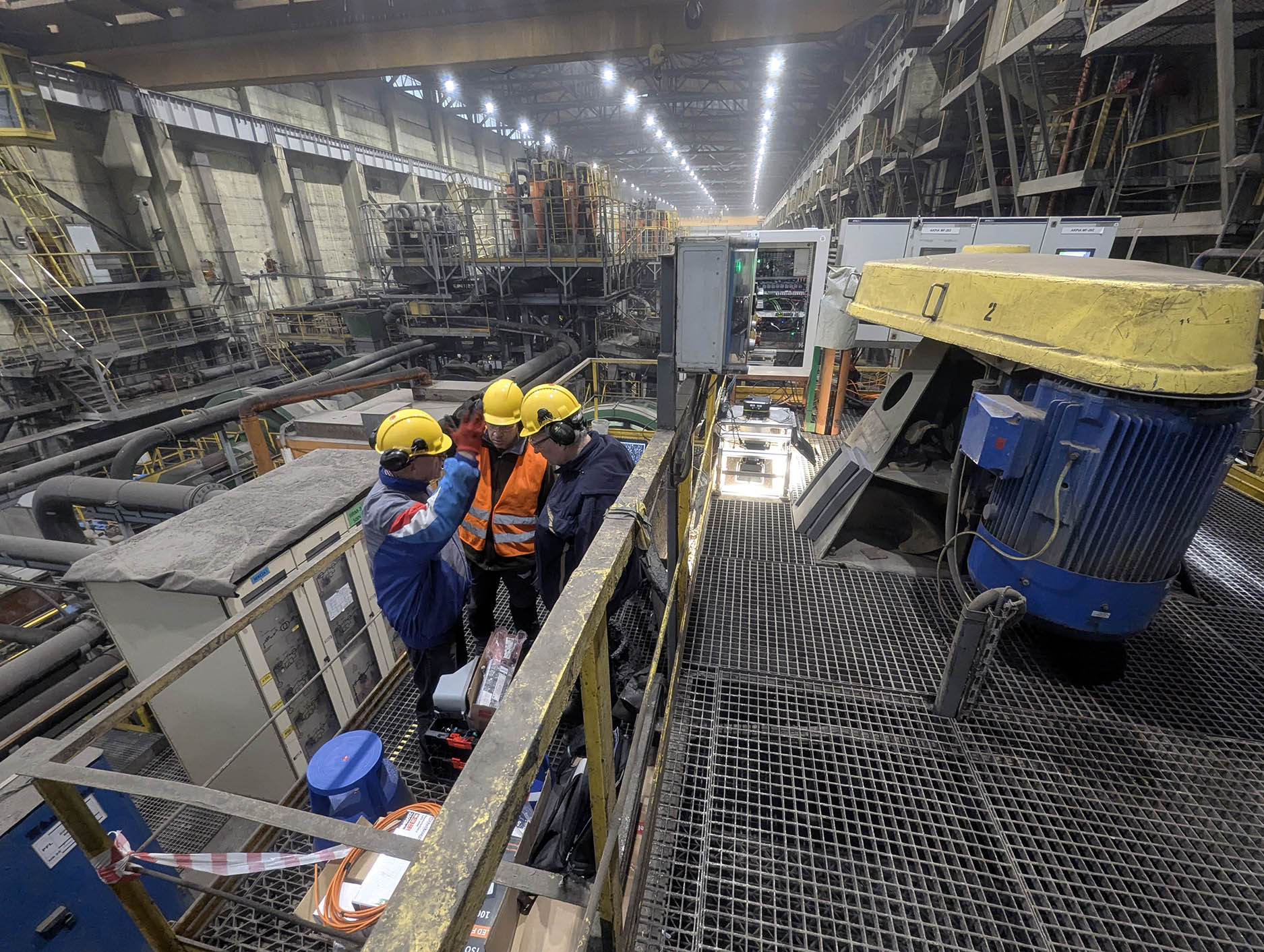
Within the project, KGHM provides the other partners with access to its technological line of the copper ore flotation, on which the metal is leached from the ore and is accumulated in the so-called flotation froth, by means of mechanical and chemical processes.
Łukasiewicz – ITR has developed and installed at KGHM the PIT System and now performs the image registration process and image processing.
Based on registered images, Łukasiewicz – ITR and Łukasiewicz – EMAG works on the ML algorithms that enable us to construct the froth image classification algorithms and then the froth content estimation. On this basis the AI algorithm for monitoring the flotation process will be developed.
AGH provides technological support for the measurement process, which will enable us the installation of the measurement system at the most appropriate measuring points and ensure the correct interpretation of the obtained results. It will also measure, using XRF techniques, the metal content of flotation froth samples collected during the froth image recording process, which is necessary for building the ML and AI algorithms.
The technology developed by the Polish partners can potentially be applied across various production facilities of different industrial groups involved in flotation processes. Among others, its industrial deployment is planned in the future at KGHM to support the optimisation of flotation technology at their plant.
Lately, the Team has determined also further changes that have to be introduced into the flotation technology for the purpose of ML process. The parameters of the flotation technological process have to be detuned from their optimal settings for the ML procedures. The interactions between the PIT System and the flotation system at KGHM during the ML and AI processes have been defined.
The PIT System consists of the PIT Visual System, PIT Illumination System, electronic unit for the PIT System functions control (PIT Image Acquisition & Illumination Control Module), the PIT Data Repository located in the PIT Server. The PIT Software includes the PIT System control module, data preprocessing module, analytical module and presentation module. The PIT System components are presented in Fig.1.
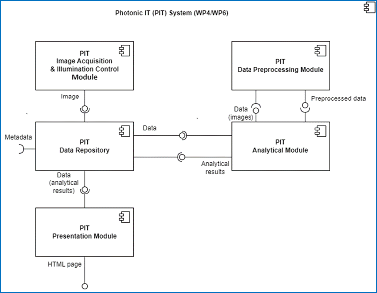
Fig.1. PIT System component diagram.
The ML and AI software is divided into the following blocks:
- The algorithms and software for the PIT System functions control.
- The algorithms and software for registration of the flotation froth images and control of the froth samples collecting process for the Machine Learning process. For this purpose more than 5 000 000 images taken from 5 various cameras has to be registered and more than 1 000 froth samples has to be collected and analyzed. Additionally, the technological parameters of the flotation process will be loaded from the flotation control system. The froth samples have to be accurately synchronized with corresponding groups of the froth images and the flotation technological parameters.
- The algorithms and Software for image processing.
- The Software for management of images, froth samples and technological parameters of the flotation process.
- The ML algorithms and software that will allow us to define the relation between the froth image and the metal content in the photographed froth. The software is developed in two ways – the software for Linear Discriminant Analysis and on the other hand the software for the Artificial Neural Network processes.
- The AI algorithms and software for estimation of the metal content in the froth.
For the Machine Learning process, the froth sampling methodology is very important, which has to be correlated with the registered images of the froth. It requires to test the short-term changes in the metal content of the froth.
For this purpose the team performed the series of detailed tests on the stability of Cu content in the Flotation Machine MF-202 destined for the Pilot process and analyzed their results. The schematic view of flotation cell with 3 Points of froth sampling is presented in Fig.2 below.
In addition to assessing the variability of the copper content in the froth, the tests carried out under industrial conditions of the flotation machine were also aimed at assessing the representativeness of the froth collection point in a specially made innovative sampler presented in Fig.2 below. This sampler collects the froth from Point 3 – the special froth sampling gutter, made for the Machine Learning purposes, which is connected to the froth observation area by the PIT Visual System. This will allow us to assess the influence of changes in the metal content vs. the image parameters. The representativeness of the sample taken in this area of the flotation machine with the sample of the final concentrate of the flotation, i.e. points 1 and 2 in Figure below, is important from the point of view of the control system efficiency.
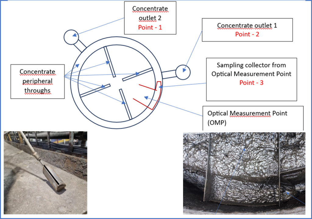
Fig.2. Scheme of the test froth sampling process.
Łukasiewicz – ITR and Łukasiewicz – EMAG have developed and carried out the first tests of the Machine Learning algorithms. Their results were presented during the 23rd Slovak-Czech-Polish Optical Conference, 02-06 September 2024, Štrbské Pleso, Slovakia and published in the Proc. SPIE.
Łukasiewicz – EMAG developed and presented the User Interface for the Pilot AI Software, which is presented in Fig. 3 below, as part of the Mine.io system within the ‘cloud services’ layer dedicated to end users and business stakeholders.
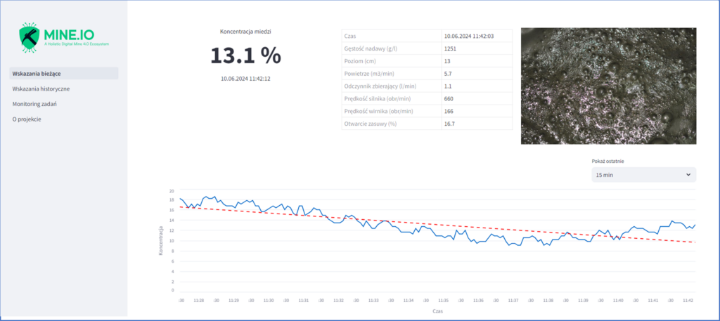
Fig.3 User Interface for the Pilot AI Software.
The PIT System has to meet the requirements of the harsh environmental conditions prevailing in the mineral processing plant, i.e. vibration, humidity, electrical disturbances, noise etc. This was a significant challenge for the system developers. All issues have been overcome and the system is now intensively tested, and it is ready for the operation during the Pilot sessions.
Installation of the PIT system in KGHM requires also meeting a number of requirements for safety and compatibility with KGHM systems. The approved project for the installation of the PIT system at KGHM has been completed.
At the beginning, during the 1-st Pilot Session, the Visual System of the PIT System was installed on the flotation machine and then intensively tested. Figure 4 presents a view of the PIT Visual System working on the flotation machine (on the left) and one of the registered images (on the right).
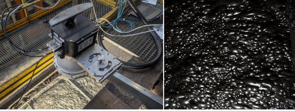
Fig.4. Visual part of the PIT System and a froth image.
The System consists of 2 multispectral cameras for VIS and IR wavelength range, 2 various monochrome cameras of different type, one color camera and the Illumination system with tailored illumination sources. All System’s components are computer controlled, which allows the operator to select the optimal registration and illumination conditions for the froth images.
The initial tests revealed that the multi-camera vision system worked very well, however the mounting facilities of the Vision System on the flotation machine required some changes due to the too high amplitude of the System vibrations. For these reasons, the mechanical part of the Vision System on the flotation machine was redesigned.
After the corrections were made, during the 2-nd Pilot Session, the complete 2-nd version of the PIT System was then installed on the flotation machine (Fig.5).
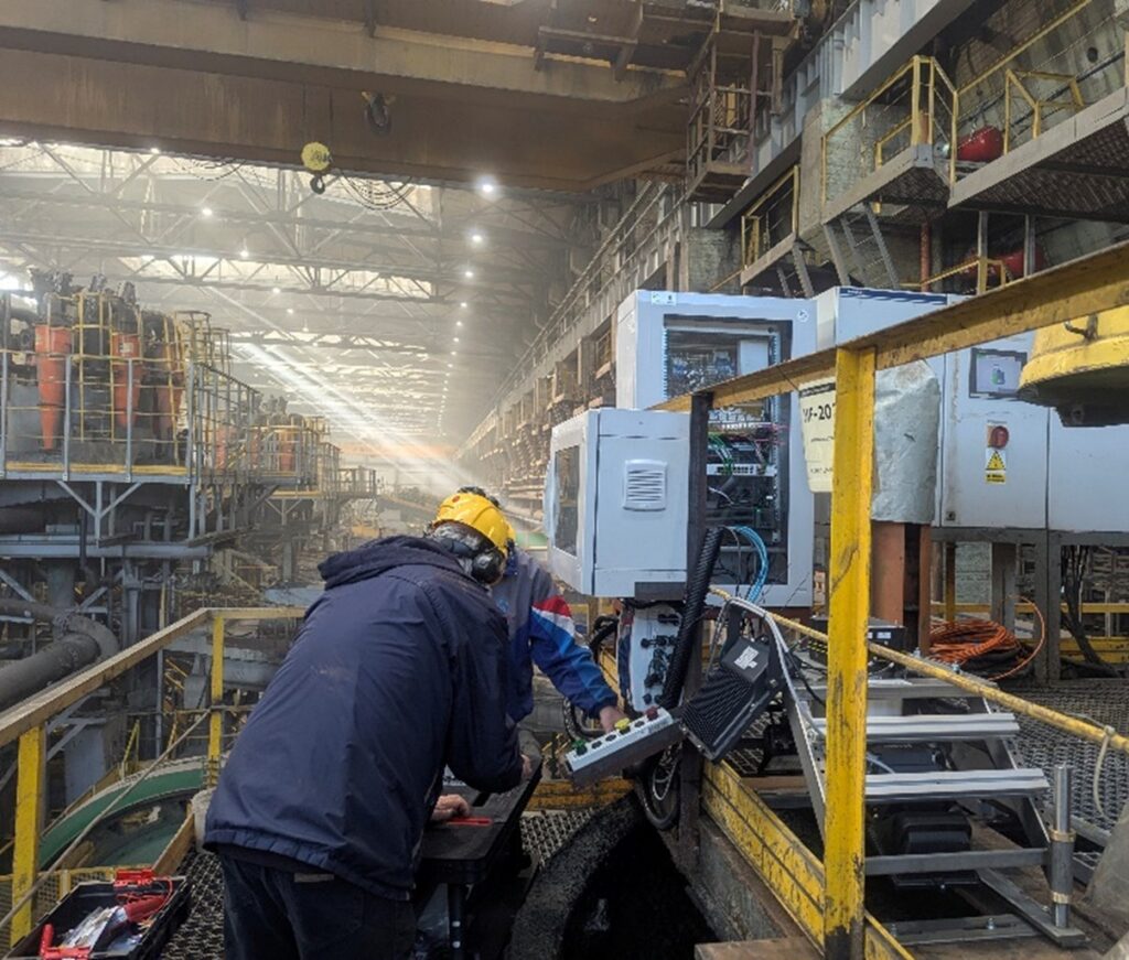
Fig.5 PIT System installation process.
The components of the PIT System is presented in Fig.6.
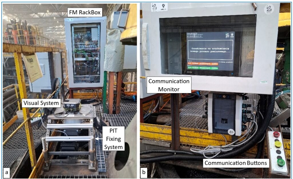
Fig.6. PIT System components: Visual System, Mounting System, Flotation Machine RackBox (a), Communication Monitor and Communication Buttons (b)
The second part of the PIT System that includes Control Room RackBox for communication components and Server are placed in the Flotation Process Control Room.
The complete PIT System was then tested in the industrial conditions. We tested the quality of communication and data links between system’s components, the quality of data channels, especially the visual channels, the methodology of communication between the Server Operator in the Control Room and the Froth Sampling Operator (Sampling Operator) on the flotation machine. After the tests we decided to use the optical fiber links instead of electrical wire ones to avoid the high level of electrical interference on the electrical lines.
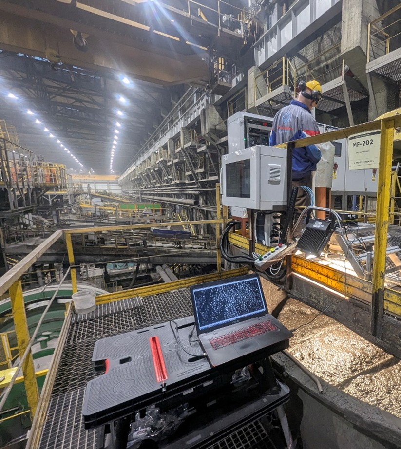
Fig.7 The PIT System during tests.
Because of the very high level of noise in the flotation hall the visual communication between the Server Operator and the Froth Sampling Operator via the Communication Monitor and manual via three color buttons was designed. Communication Monitor displays the information and commands for the Sampling Operator. The Monitor displays the information when the Sampling Operator should insert a new container for a new Collective Froth Sample, inform him that the registration of the new group of images is started and next – the commands to collect the subsequent froth samples.
The communication buttons allows the Sampling Operator to send messages to the Server about the readiness for the froth sampling, confirmation that the sample has been collected and that the registration of the group of images and the froth sampling processes have to be stopped.
To establish the methodology of the froth sampling process the flow size of the froth from the flotation machine to our sampler and the froth content stability from the area observed by the PIT System has been measured. As a result of the data received, it was decided to collect 3 temporary froth samples collected during 1 sec each at the time intervals equal to 1 minute for 1 collective froth samples.
On this basis, the 3-rd Pilot session was carried out. After some changes to the measurement system, during this session we collected 106 collective froth samples (1 collective sample every 6 minutes). The froth content was measured by the calibrated XRF method.
That the flotation process is highly unstable. Since the level of fluctuations of the Cu content in time is high the flotation process optimization becomes very important for the efficiency of the flotation technology.
During this session over 180 000 froth images in 100 groups was registered. Now the images are digitally processed to prepare them for Machine Learning processes. Two approaches of ML will be applied: the Linear Discriminant Analysis and Artificial Neural Networks.
One of the results of the multispectral froth image processing in the IR wavelength range is presented in Fig.8 below.
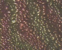
Fig.8 Multispectral froth image processing in the IR wavelength range.
The multispectral image processing has revealed that the distribution of Cu compounds over the froth surface is not uniform which is illustrated by the surface colors (the colors are artificial). This may be the topic of investigation of the flotation technology optimization process.
The next stage of the work carried out by Łukasiewicz – EMAG involved the generation and evaluation of models for predicting the value of metal concentration in the flotation froth. The analysis was carried out on historical data from a sphalerite/galena processing plant. Different data representations describing the flotation process were included in the research carried out – images of the flotation froth and flotation process parameters were analyzed. The generated predictive models were trained on each of these representations separately, and models were generated by performing different types of representation fusion. Representation fusion (images and tabular data) was also carried out at different levels of a deep neural network. The results obtained are being developed for publication as a journal article.
The up to now obtained project results were published in 5 research papers and scientific conferences as well as in the social media presentations.
WP4 – Technological solutions for strategic processingand waste management
T4.3 Artificial Intelligence technology for monitoring, control of metal ore processing (Leader: LITR, Participants: LEMAG, AGH, KGHM)
Stay tuned, more articles from the Progress Work Campaign series will be coming soon…


Leave a Reply